The Key Components of Battery Energy Storage Systems (BESS)
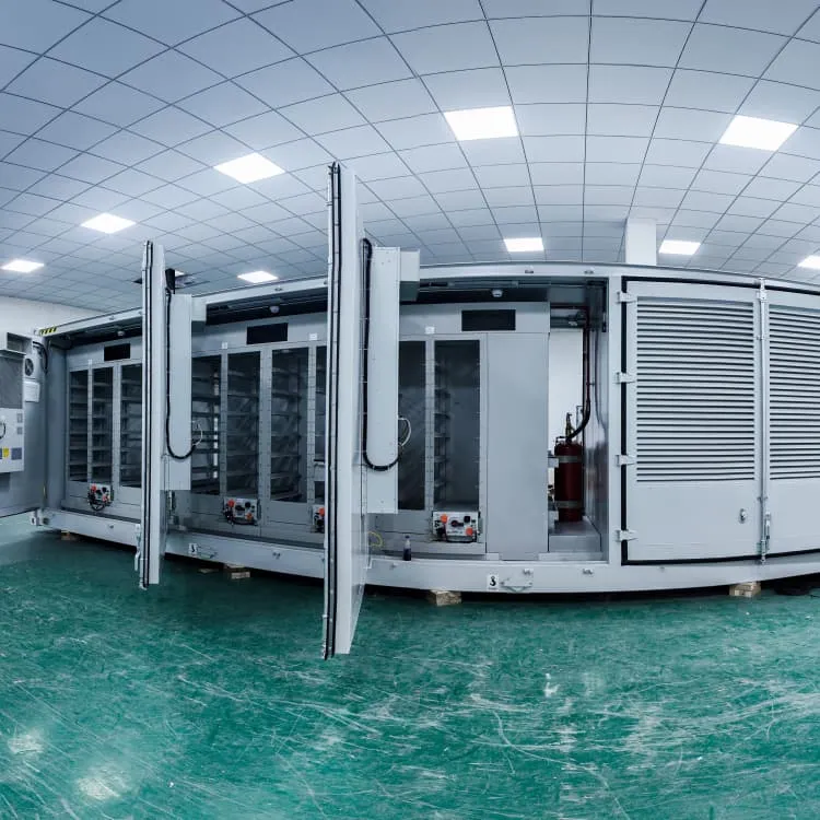
Several modules create a battery rack, and multiple racks are connected to form battery banks or arrays, constituting the battery side of the system. Figure 0 depicts the configuration of a BESS rack.

Energy storage cabinet assembly diagram
Structure diagram of the Battery Energy Storage System (BESS), as shown in Figure 2, consists of three main systems: the power conversion system (PCS), energy storage system and the
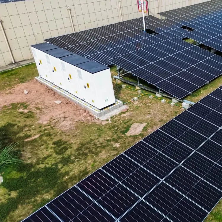
Utility-scale battery energy storage system (BESS)
This reference design focuses on an FTM utility-scale battery storage system with a typical storage capacity ranging from around a few megawatt-hours (MWh) to hundreds of MWh.
Battery Energy Storage System SLD (Single Line Diagram)
A Battery Energy Storage System (BESS) Single Line Diagram (SLD) is a core engineering document that defines the entire electrical topology, protection philosophy, control interfaces and power flow
BATTERY ENERGY
Protection against voltage fluctuations and defects on facility components. Limited use of diesel generators or gas engine to black start capabilities. Slow power plant response to grid fluctuations. Increase
Battery Energy Storage System Components
Explore the key components of a battery energy storage system and how each part contributes to performance, reliability, and efficiency.
Schematic diagram of a typical stationary battery energy storage
Schematic diagram of a typical stationary battery energy storage system (BESS). Greyed-out sub-components and applications are beyond the scope of this work.
Battery Energy Storage System Diagram: A Complete Guide to BESS
In this comprehensive guide, we will dissect the components of a battery energy storage system diagram, explore the differences between AC and DC coupling, and help you identify the right configuration
Battery energy storage system assembly rack diagram
Battery racks can be connected in series or parallel to reach the required voltage and current of the battery energy storage system. These racks are the building blocks to creating a large,high-power BESS.
BATTERY ENERGY STORAGE SYSTEMS (BESS)
A battery system is a complete energy storage system that plays a key role in renewable energy success by helping to balance renewable energy supplies with electricity demands.
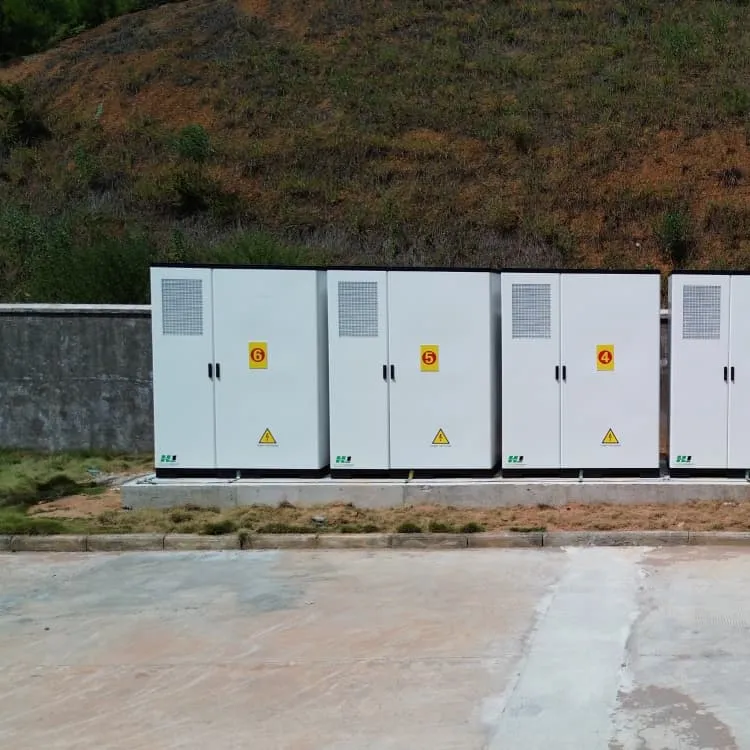
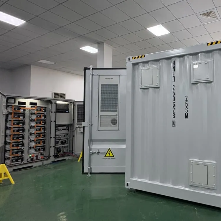
BESS Containers
20ft/40ft BESS containers from 500kWh to 5MWh with liquid cooling, grid-forming inverters – ideal for utility and industrial microgrids.
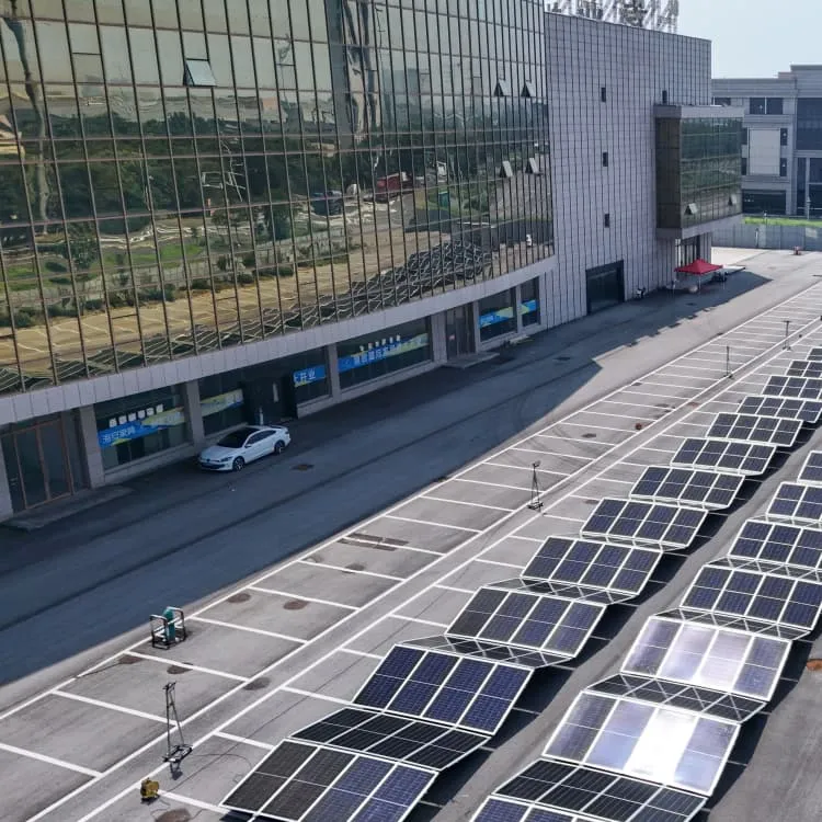
Industrial Microgrids
Complete microgrid systems with islanding, genset integration, and real-time optimization – reducing diesel consumption and improving reliability.
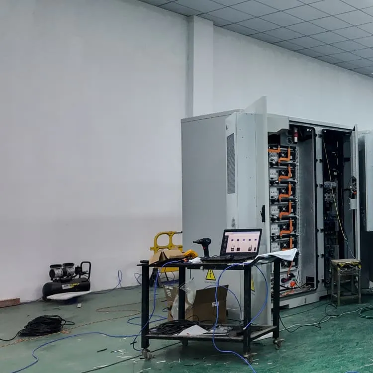
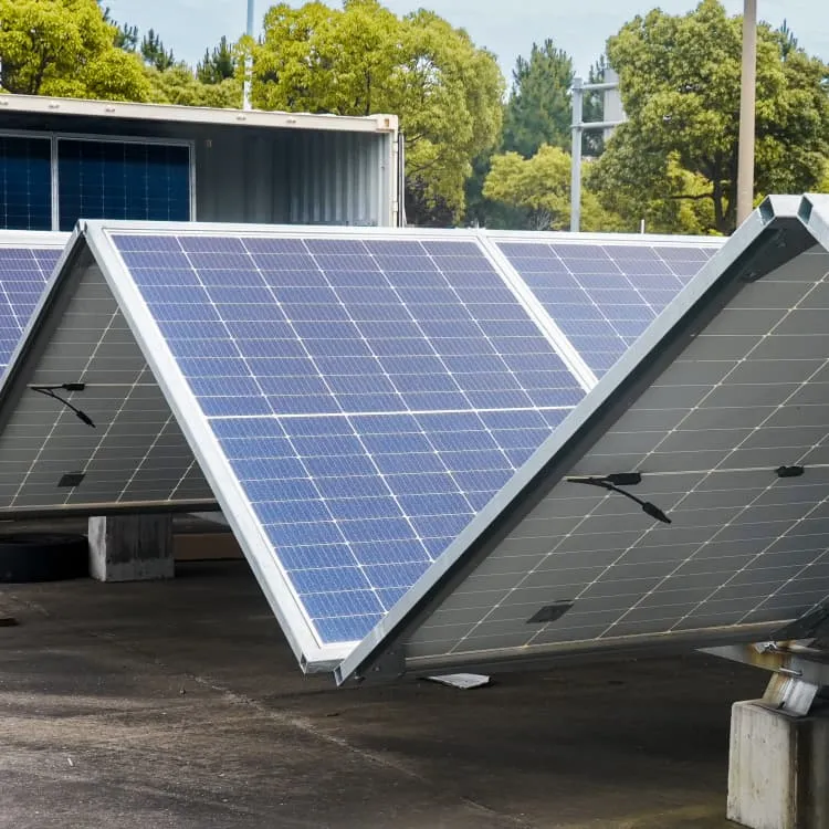
PV & Foldable Containers
Plug-and-play photovoltaic containers with foldable solar arrays (10–200kWp) for rapid deployment in remote areas and off-grid microgrids.
Telecom Tower ESS
48V LiFePO4 battery storage and DC power systems for telecom towers – reduces diesel runtime and ensures 24/7 uptime.