4 Frequently Asked Questions about “Structural diagram of the wind chamber of the steam turbine generator - SCM INDUSTRIES BESS”
What is a steam turbine diagram?
A steam turbine diagram typically illustrates the various components and stages of a steam turbine system, including the flow of steam and energy conversion. While steam turbine diagrams can vary in complexity and detail, here is a simplified representation of a basic steam turbine system:
What are the components of a wind turbine?
Nacelle. This contains all the components that sit on top of the tower, except the rotor system. It includes main shaft, gearbox, generator, brake, bearings, nacelle frame, yaw mechanism, auxiliary crane, hydraulic system, and cooling system. 1. Rotor System The rotor system captures wind energy and converts into rotational kinetic energy.
What are the components of a steam turbine?
The basic components of a steam turbine include: Rotor: The rotor is the rotating part of the turbine that converts the steam's kinetic energy into mechanical work. It typically consists of multiple blades or buckets attached to a central shaft. Stator: The stator is the stationary part of the turbine that contains fixed blades or nozzles.
What are the governing parameters for steam turbine design?
Steam conditions, particularly temperature, are limited by material properties while pressures are often dictated by the steam supply system. The result is that the governing parameters for turbine design are generally fairly standard and most manufacturers design their turbines within rather narrow limits.
STEAM TURBINES
Step 1 Calculation of the steam turbine stage I. the heat drops II. dummy velocity of steam flow III. average diameter of the stage skirting IV. actual steam velocity at the outlet of the

STEAM TURBINE GENERATORS
This chapter provides a general overview of steam turbine generators. The detailed design of individual components is not addressed since typically the power plant designer is not
Steam Turbine Diagram
Steam Turbine Diagram A steam turbine diagram typically illustrates the various components and stages of a steam turbine system, including the flow of steam and energy
Parts of a Steam Turbine
Steam turbines serve as integral components in the petrochemical, power generation, and refinery industries. The foundational architecture of a steam turbine comprises a rotor, precision
How a Wind Turbine Works
Learning how a wind turbine works is easy as long as you first make sure to know how a turbine generator works. The diagram of the wind turbine above is a side view of a horizontal axis
Steam Turbine Components and Systems
The rotor is fitted inside the casing with the rows of moving blades penetrating between the rows of fixed blades. Thus steam flowing through the turbine passes alternately through fixed and
An overview of the structure of wind turbine generators
Download scientific diagram | An overview of the structure of wind turbine generators from publication: Large‑scale wind power grid integration challenges and their solution: a detailed review

Microsoft PowerPoint
These structural elements carry all the forces and moments to the ground 2. Nacelle. This contains all the components that sit on top of the tower, except the rotor system. It includes main

Microsoft Word
The design of Steam Turbine is influenced by factors, including process requirements, economics and safety. This engineering design guideline covers the basic elements of Steam
Design And Analysis Of Steam Turbine
In power generation mostly steam turbine is used because of its greater thermal efficiency and higher power to weight ratio. Because the turbine generates rotary motion, it is
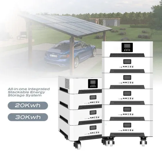
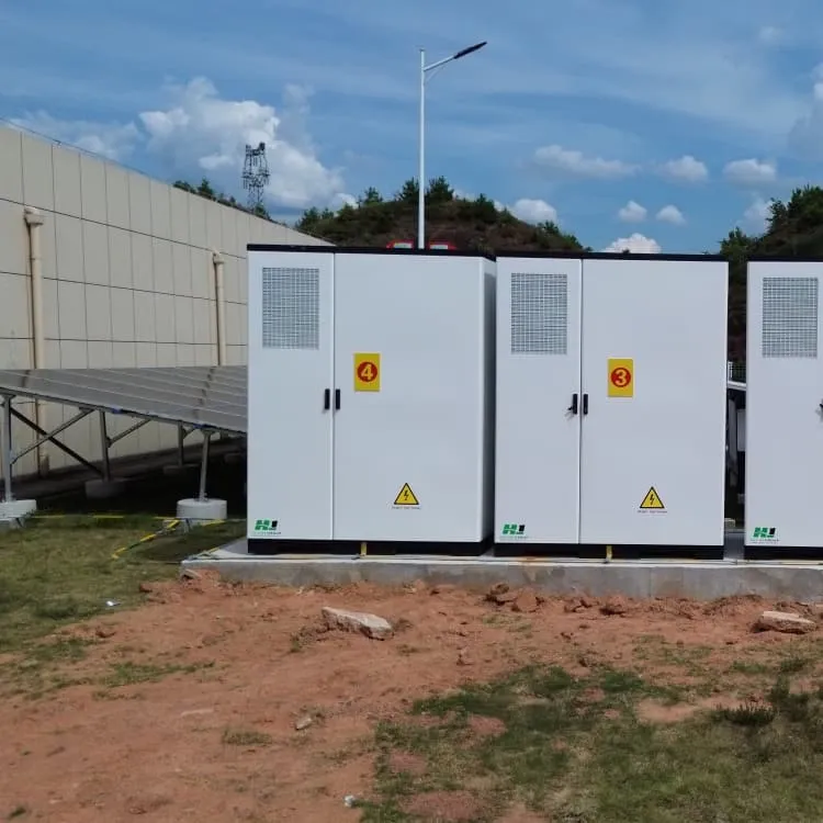
BESS Containers
20ft/40ft BESS containers from 500kWh to 5MWh with liquid cooling, grid-forming inverters – ideal for utility and industrial microgrids.
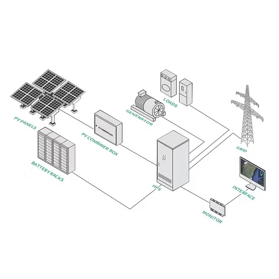
Industrial Microgrids
Complete microgrid systems with islanding, genset integration, and real-time optimization – reducing diesel consumption and improving reliability.
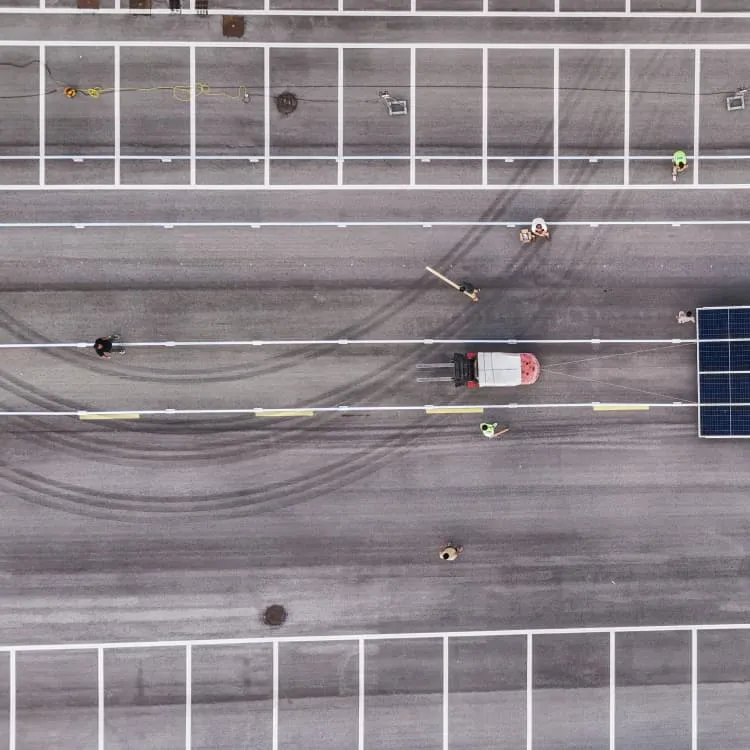
PV & Foldable Containers
Plug-and-play photovoltaic containers with foldable solar arrays (10–200kWp) for rapid deployment in remote areas and off-grid microgrids.
Telecom Tower ESS
48V LiFePO4 battery storage and DC power systems for telecom towers – reduces diesel runtime and ensures 24/7 uptime.