Circuit Diagram of a PV System with Storage: Professional
A well-planned circuit diagram of a PV system with storage is crucial for the efficient and safe operation of the system. It outlines how components are interconnected, ensuring optimal

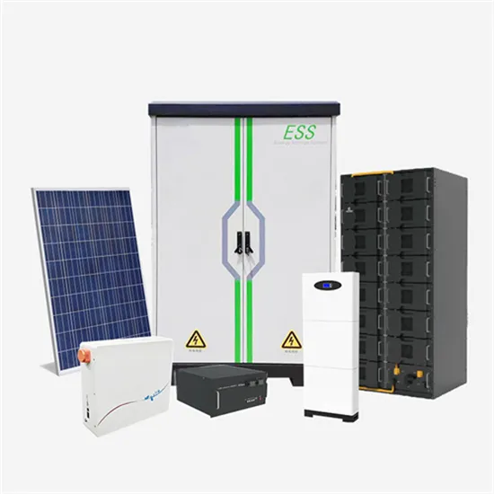
Solar Energy Storage System Diagram Explained
Explore the key components of a solar energy storage system diagram and how Tsun ESS solutions optimize renewable power storage.
Planning Guidelines
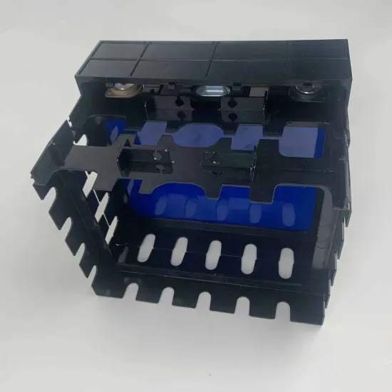
A lithium-ion battery is especially suited for intermediate storage of PV energy due to its high cycle stability. The lithium-ion batteries must be compatible with the Sunny Island:
Schematic of the photovoltaic and battery storage systems (BESS).
As PV technology and energy storage costs continue to decline, both technologies will likely play an increasingly important role in the renewable energy sector.

Utility-scale battery energy storage system (BESS)
This reference design focuses on an FTM utility-scale battery storage system with a typical storage capacity ranging from around a few megawatt-hours (MWh) to hundreds of MWh.
Understanding the Solar Energy Storage System Diagram: A
A detailed solar energy storage system diagram breakdown, explaining components, configurations, and design principles for achieving energy independence.

Schematic diagram
Schematic diagram Input 1: 1 string of 5 *HIH* Longi HiMo5 405W Mono PV panels (Black Frame White Backsheet) Input 2: 1 string of 6 *HIH* Longi HiMo5 405W Mono PV panels DC isolators 9.60 kWh 4
Understanding Energy Storage Photovoltaic System Diagrams: A
As researchers crack the code on perovskite solar cells [10] and virtual power plants go mainstream, one thing''s clear: The energy storage photovoltaic system diagram isn''t just technical
Battery Energy Storage System Diagram: A Complete Guide to BESS
In this comprehensive guide, we will dissect the components of a battery energy storage system diagram, explore the differences between AC and DC coupling, and help you identify the right
New energy storage cabinet schematic diagram explanation
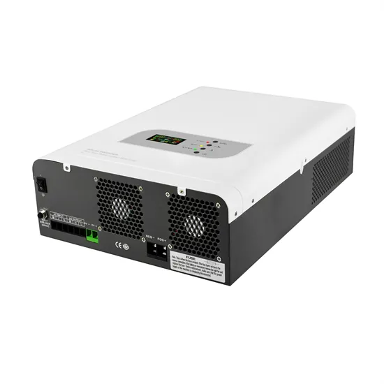
Structure diagram of the Battery Energy Storage System (BESS), as shown in Figure 2, consists of three main systems: the power conversion system (PCS), energy storage system and the
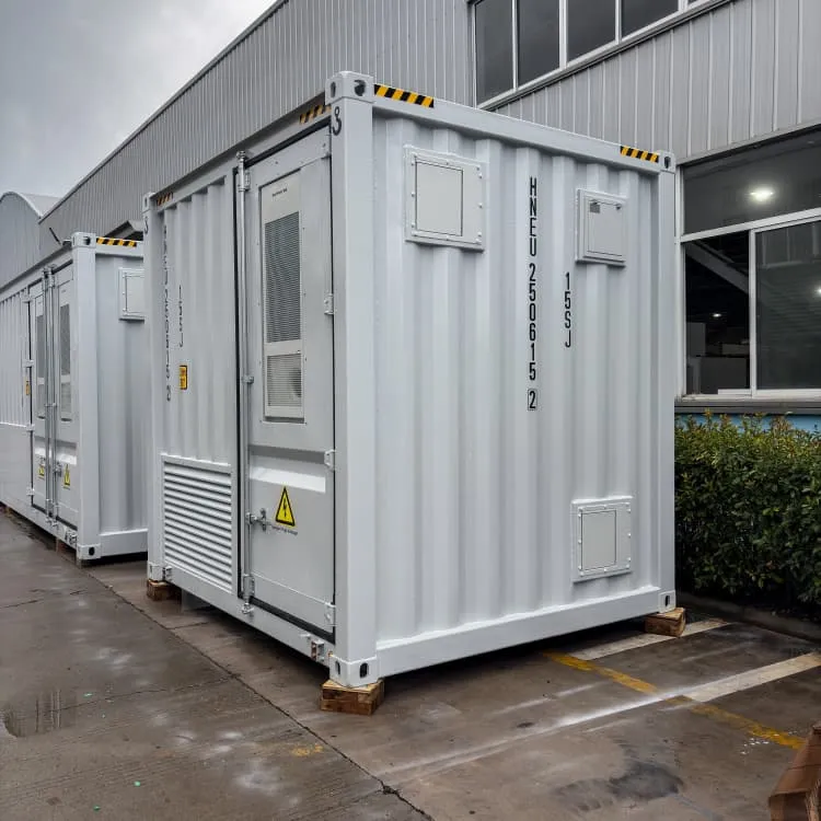
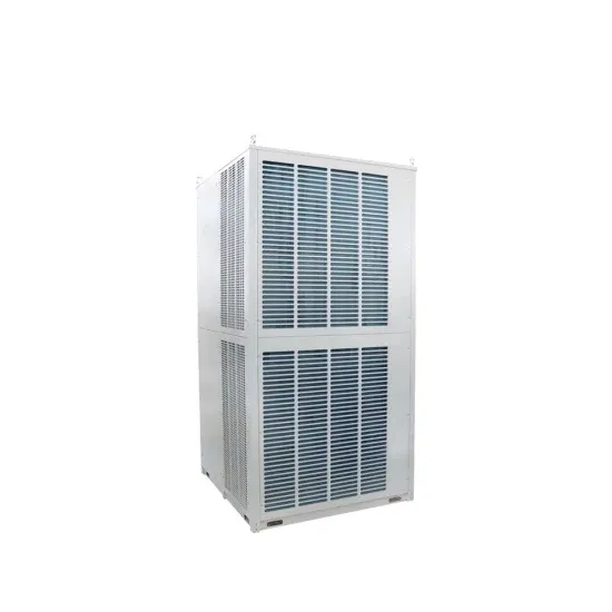
BESS Containers
20ft/40ft BESS containers from 500kWh to 5MWh with liquid cooling, grid-forming inverters – ideal for utility and industrial microgrids.
Industrial Microgrids
Complete microgrid systems with islanding, genset integration, and real-time optimization – reducing diesel consumption and improving reliability.
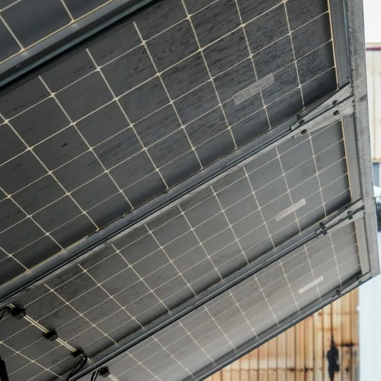
PV & Foldable Containers
Plug-and-play photovoltaic containers with foldable solar arrays (10–200kWp) for rapid deployment in remote areas and off-grid microgrids.
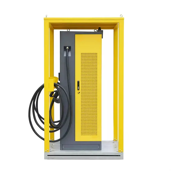
Telecom Tower ESS
48V LiFePO4 battery storage and DC power systems for telecom towers – reduces diesel runtime and ensures 24/7 uptime.